Miller Indices
Last Updated: 23rd Aug 2021By Donald Peck & Erin Delventhal
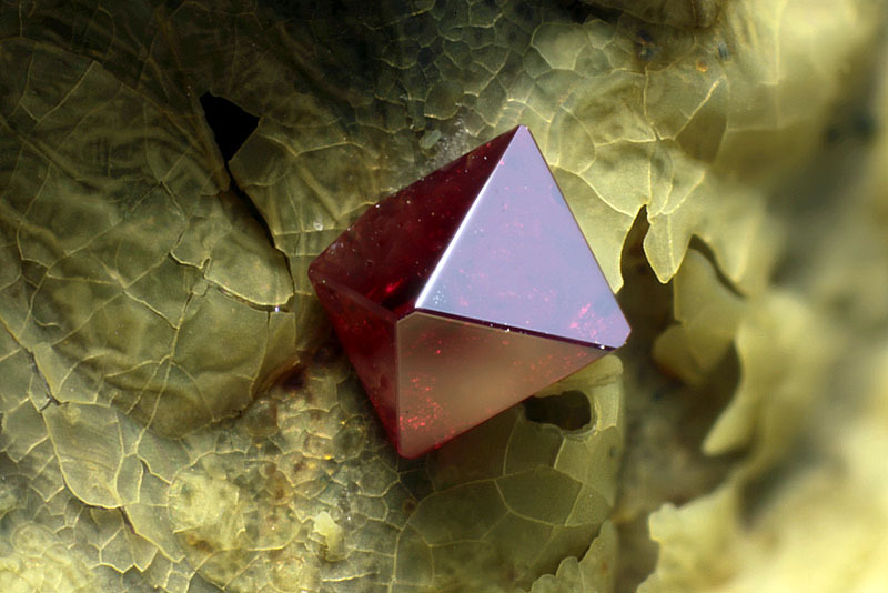
Cuprite
What is a Form? How are Miller Indices related to Forms? What is a Face? What are the Miller indices for each Face that you can see?
Answers are at the end of, or in, this article.
Miller Indices are often a mystery to mineral collectors. They need not be, for they are quite simple in concept (if not in mathematics). In this paper, we will feature a conceptual approach, and ignore the mathematics.
In the 19th century, goniometry (the measurement of crystal angles) was a major part of mineralogy. As technologies for analyzing minerals by chemistry were in their infancy, there was a need for identifying the various faces on crystals as a means of identifying the mineral itself. In 1839 William Miller, a British mineralogist, proposed his system for indexing. Other systems had been proposed to accomplish the same end, but they were unwieldy. Miller developed his system as an improvement and a simplification. Miller Indices were widely accepted and remain important to the science of crystallography today. They describe not only the relationship of crystal faces to crystallographic axes, but the relationship, as revealed by x-rays, of internal atomic planes to the axes, the unit cell, and ultimately the faces of the crystal.
Basic Concepts
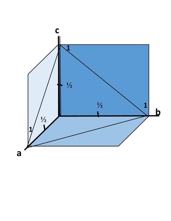
Unit Plane
1. All planes that are crystal faces can be related in a simple way to the axes of the crystal by a Unit Plane, which is illustrated at right by the transparent triangle (remember, this is a plane in three dimensional space). (Click the image to enlarge it.)
2. The unit plane intercepts each of the crystal axes at a Unit Distance. The unit distance is 1 (one).
3. Except in the isometric system, the unit distances on different axes may have different absolute lengths. (i.e. 1 on the a-axis may be and usually is a different absolute length than 1 on the c-axis). The unit distances on axes and axial angles are constrained by symmetry.
4. Relative unit distances are reported as the Axial Ratio of the crystal. (e.g. in baryte, an orthorhombic mineral, the axial ratio is a:b:c = 1.628 : 1 : 1.312. The a-axis is the longest while the b-axis is the shortest.
5. All planes that are crystal faces and that intercept the crystallographic axes, can be represented to do so either at a unit distance, or some fractional value of the unit distance.
The Miller Indices
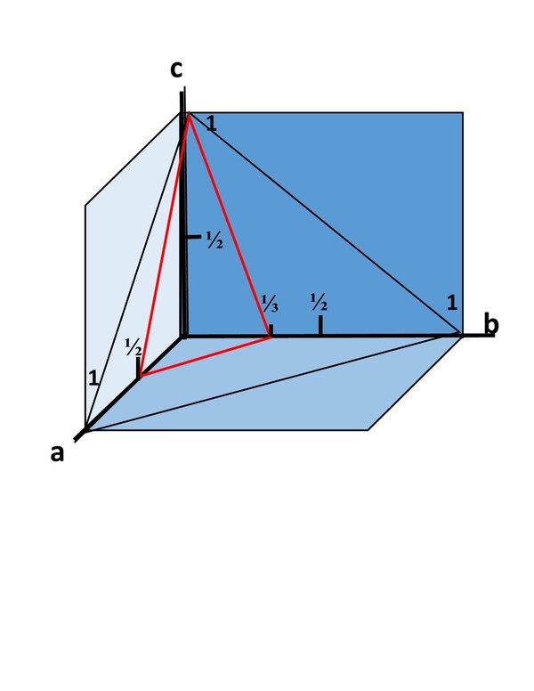
231 Plane
The Miller Indices are a series of numerals that relate the particular crystal face to the Unit Plane on the crystallographic axes. In all but the Trigonal and Hexagonal Crystal Systems, the indices are three digits in a, b, c order. In the Trigonal and Hexagonal systems they are four digits in a1, a2, a3, c order. An index is a single digit, indices are the set of three or four digits.
The Miller Indices of the unit plane are (111), read as "one, one, one", not "one hundred eleven".
An intercept on an axis is always 1 or less. For mathematical reasons that we are avoiding, when an intercept is ½ the unit distance on an axis, the Miller index is 2. If the intercept is ⅓ the index is 3. In other words, the Miller index of the intercept on an axis is the reciprocal of the fraction of the unit distance. If the intercepts on the a-axis = ½, on the b-axis = ⅓, and on the c-axis = 1, the indices for that face are (231). (Click the illustration at right to enlarge it.)
If the plane of the face is parallel to an axis, and does not intercept it, the index for that axis is 0. Thus a face that intercepts the a-axis at 1, the b-axis at 1, and is parallel to the c-axis has Miller indices of (110). If the face intercepts only the a-axis at 1 and is parallel to both b and c, the indices are (100).
If the crystal face intercepts the negative end of any axis, a bar is placed over the index for that axis. For example, when a face intercepts are a = 1, b = 1, and c = -1 the Miller indices for that face are (111), read as "0ne, one, bar one."
The unit plane itself is often visible on a crystal. It is the face that cuts off the top right front corner of a cube (oriented as you are viewing a front square face) or a similar corner on tetragonal, orthorhombic or monocolinic crystals. It has indices of (111). In theory, all other faces on the crystal are indexed from this one.

Hexagonal pyramid
The face shown at the right, on the four-axes of the hexagonal and trigonal systems, is a pyramid with the Miller indices of (1011). It would be directly above the prism face, (1010). The third numeral is always the sum of the first two numerals multiplied by -1 (e.g. sum the first two digits and change the sign). Note the directional signs of the a-axes. They result from an angle of 120o between a-axes, not 60o.
Summary
1. Miller indices are three digits in a, b, c order; or in the hexagonal or trigonal crystal systems four digits in a1, a2, a3, c order.
2. If an index is 0 then the plane of the crystal face is parallel to the respective axis. Face (110) is parallel to the c-axis.
3. The value of an index is always an integer, 1, 2, 3, 4, 5 or higher (higher is very unusual).
4. A bar over an index indicates that the intercept is on the negative end of the respective axis. Face (110) intercepts the negative (back) end of the a-axis.
5. The greater the value of an index, the the smaller the angle between the face and that axis.
1. Orient the model with the following settings: Miller Indices: ON, Axes: ON, Transparency: OPAQUE, View: ALONG A-AXIS.
2. Place the Cursor on b of the b-axis, hold down the left button on the mouse and slowly move straight across the center of the model.
As each new face appears, can you explain the Miller Indices for the face?
3. Click Along a-axis (to square up the model image). Repeat steps 2 but with the cursor on the c of the c-axis and pulling straight down.
Try your skill with some other habits of fluorite (remember to toggle on the Miller Indices and the axes):
In Figure 2, which face is the Unit Plane and how is it related to the other seven faces?
In Figure 3, if you understand symmetry, examine the distribution of indices each side of mirror planes and around 4-fold and 3-fold axes of rotation.
In Figure 4, the beveled edges of the square faces have 5 parallel faces; check the summative properties of adjacent face Miller indices. How are the five faces related to each other? Notice the triad of faces at each corner of the cube compare the indices to each other and to the other faces they contact.
In Figure 5, do the same with this model. Notice that, oriented to the a-axis, 221 + 221 = 440. 440 is not 110, but 440 and 110 are parallel planes, When considering crystal morphology, stacked atomic planes all have the same indices - in this case 440 is 110.
Faces, Forms & Zones... and Brackets
You may have noticed, that Miller indices in text are enclosed in parentheses, (110). This is a common convention for a crystal face, but one not always followed. Forms and zones are designated also by Miller indices, and are differentiated in print by their own brackets. A form is enclosed in curly braces, {110}, and a zone in square braces: [110].

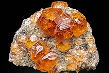
Almandine
A crystal face is a flat, or plane, surface that bounds a crystal and that is not formed by contact or interference from another crystal or surface.
A face is considered to be infinite in its extent. The shape we see is constrained by its intersection with surrounding faces.
A garnet often shows 12 rhomb shaped faces, one of which has the Miller indices, (101). As you can deduce, the (101) cuts the a1 and a3 axes at unit distances and is parallel to the a2 axis. As shown, above, the vertical diamond shaped face in front would be indexed as (101). The face to its left, (011). The face behind (over the top) would be (101).
A crystal form is a set of faces that all have the same relationship to the crystallographic axes.
In an ideal, or perfectly formed crystal, if one face of a form exists , the axes of rotation and the mirror planes require that every face in the form shall exist. For example, if you find one rhombic face intersecting two axes and parallel to the third axis on a crystal in the cubic system, the symmetry demands that there must be eleven more of them. The symmetry requires a total of twelve faces for cubic form {101}, the rhombic dodecahedron.
The Miller Indices for a form are taken from a face on the upper right front octant or front of the crystal.
A crystallographic zone is defined by its axis and is a direction. The Miller Indices of the zone are those of the face which is perpendicular to the zone axis.
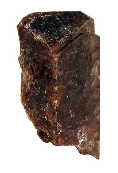
Andalusite
Note: The Andalusite crystal at right is orthorhombic and is oriented with its c-axis vertical, b-axis horizontal and left to right, and a-axis front to back. The c-axis is a zone axis (so are the a-axis and b-axis, but with no lower termination, this cannot be seen on the crystal shown).
Generalizing Miller Indices
There are times when we wish to generalize the Miller indices rather than be specific. In such cases, h is substituted for the index on the a-axis, k for the index on the b-axis, and l for the index on the c-axis. The general indices for any face then are (hkl). If we wish to specify all faces parallel to the a-axis, the general indices are (0kl); parallel to the b-axis, (h0l); or parallel to the c-axis, (hk0).
In the trigonal and hexagonal crystal systems, an i is inserted to generalize the third digit. Generalized indices for these systems are (hkil).
Useful Relationships
The greater the value of an index on a given axis, the steeper the inclination of the face to that axis.
The result of adding the indices for faces separated by a third face in the same zone is always the indices of a possible face. When there are three contiguous faces in the same zone (that meet with parallel edges), the Miller indices of the middle face are quite probably the sum of the indices of the faces on either side. For example, if the indices of the bracketing faces are (100) and (010), the middle face is likely to be (110). If the Miller indices of the two bracketing faces are (221) and (221), the most probable indices for the face between them are (440); but 440 is a parallel plane to 110, which is the intervening face. Parallel planes all have the same indices, and they are the simplest possible: 100, 200, 300 are all 100; 111, 222, 333 are all 111; etc.
In the hexagonal and trigonal crystal systems, the Miller indices traditionally have been four digits, as (1011). Both systems can be represented in a three digit model, however the four digit model is arguably easier to visualize. The third digit is redundant and present day crystallographers are switching to the three digit system. The value of the third digit is always the negative sum of the first two digits. If the indices for a face are (1011) then the third digit is dropped and they become (101). If crystals in either of those systems are described using 3-digit Miller indices, and you prefer the 4-digit system, merely sum the first two digits of the indices and reverse the sign to obtain and insert the third of the four indices.
The Role of the Axial Ratio
The axial ratio for a crystal is the relative dimensions of the unit cell.
For cerussite, an orthorhombic mineral, the axial ratio is a:b:c = 0.61 : 1 : 0.723. That is, in absolute lengths the unit a-axis is 0.61 times the length of the unit b-axis and the unit c-axis is 0.723 times the length of the unit b-axis. The b-axis is longest and the a-axis is shortest.
The dimensions of a crystal are often inverse to the dimensions of the unit cell. If the c-axis is the shortest dimension of the unit cell, it is often to be the longest dimension in the actual crystal.
Assigning Miller Indices to Crystal Faces
If you should have a crystal on which you want to index the faces, the first task is to decide how to orient the crystal and then to assign the crystallographic axes. This usually means that you have to decide in which of the seven crystal systems your specimen belongs (symmetry can be a major help). Then orient the crystal. If there is a long dimension, it is usually the c-axis and is placed in a vertical position. Most often the b-axis is longer than the a-axis and is horizontal, left to right. The tetragonal, trigonal, and hexagonal systems present a problem with orientation. Most often, but not always, the a-axes emerge from the edges of the prism faces, not the center of the {100}. With an unknown mineral crystal, unless the termination provides a clue, the best you can do is guess (upon further information you can always change it).

Common Crystal Faces
The second task is to sketch your crystal. Make a map of the upper termination. Then try to draw an oblique view in 3D of the crystal.
There are certain forms that are persistent across crystal systems. The {100} form, or the (a) face, is almost universal. The {001}, or (c) face, and the {010}, the (b) face, are nearly as common. The {111} unit form clipping the corners, when present, is usually easy to see. and the {110}, or (m) face, is very common, beveling vertical edges. Look for them. And if you find them, assign the indices and write them onto your drawings.
Then using what you know of the relationships between the indices of adjacent faces, make a guess at the indices for the intervening faces,
Until you find a drawing for your crystal in a reference book or on the web, you will not have anything better, and when you find that your analysis is correct, well, that is a very satisfying feeling.
Miller Indices of the Cuprite Crystal at the Top of This Article

Cuprite (click photo to enlarge it).
1. First we will orient the crystal. It is essentially equal in all dimensions. Each point is on an axis of 4-fold symmetry, and there is more than one of them, so the crystal is in the isometric (cubic) system. We will make the axis from the point at the center of the photo to the back (unseen) the a1 axis. The a2 axis will run from right (+) to left (-). And the a3 axis is from top (+) to bottom (-), tilted slightly to the right at the top.
2. The small orthoganal face at the front of the crystal (center of photo) is a rectangle due to uneven growth. The ideal shape of the form is square. The Form is the {100}, the cubic form. The face is the (100).
3. The large triangular faces intersect each edge of the rectanglar cubic face. They are the [111} form, the octahedral form. We will assign the bright face at the right as the (111); the face at top left is the (111); the very dark face at lower left is the (111); and the slightly shadowed face at the bottom is the (111).
3. The narrow faces beveling the edges between the triangular faces are the {101). The face that bevels the edge between the (111) and the (111) is the (110). It cuts the a1 and a2, but not the a3. The thin face that can be seen on the top right edge of the crystal is the (011). The (101) is at the left edge of the (111). What are the indices of the face between the (111) and the (111)?
Links to the Crystallography Series
Crystallography: The Triclinic SystemCrystallography: The Monoclinic System
Crystallography: The Orthohombic System
Crystallography: The Trigonal System
Crystallography: The Hexagonal System
Crystallography: The Tetragonal System
Crystallography: The Isometric System
References
Smith, Jennie R. (1991) Understanding Crystallography. The Rochester Mineralogical Symposium. pp 66-78
Peck, Donald B. (2007) Mineral Identification: A Practical Guide for the Amateur Mineralogist. Mineralogical Record, Tucson, Arizona. pp 63-64
Dana, Edward Salisbury, Ford, William E. - Editor (1991) A Textbook of Mineralogy. John Wiley & Sons, Inc., New York
Mason, Brian and Berry, L.G. (1968) Elements of Mineralogy. W. H. Freeman and Company, San Francisco. pp 19-28
https://en.wikipedia.org/wiki/Miller_index Wikipedia.
https://en.wikipedia.org/wiki/Crystal_structure Wikipedia
Acknowledgements
Photos are from Mindat files. We are indebted to Chinellato Matteo, Allesandro Tagliaferri, and Dan Weinrich for sharing them with us.
Article has been viewed at least 45763 times.


Quick NavBasic ConceptsThe Miller IndicesFaces, Forms & Zones... and BracketsGeneralizing Miller IndicesUseful RelationshipsThe Role of the Axial RatioAssigning Miller Indices to Crystal FacesMiller Indices of the Cuprite Crystal at the Top of This ArticleLinks to the Crystallography SeriesReferencesAcknowledgements


