Home PageAbout MindatThe Mindat ManualHistory of MindatCopyright StatusWho We AreContact UsAdvertise on Mindat
Donate to MindatCorporate SponsorshipSponsor a PageSponsored PagesMindat AdvertisersAdvertise on Mindat
Learning CenterWhat is a mineral?The most common minerals on earthInformation for EducatorsMindat ArticlesThe ElementsThe Rock H. Currier Digital LibraryGeologic Time
Minerals by PropertiesMinerals by ChemistryAdvanced Locality SearchRandom MineralRandom LocalitySearch by minIDLocalities Near MeSearch ArticlesSearch GlossaryMore Search Options
The Mindat ManualAdd a New PhotoRate PhotosLocality Edit ReportCoordinate Completion ReportAdd Glossary Item
Mining CompaniesStatisticsUsersMineral MuseumsClubs & OrganizationsMineral Shows & EventsThe Mindat DirectoryDevice SettingsThe Mineral Quiz
Photo SearchPhoto GalleriesSearch by ColorNew Photos TodayNew Photos YesterdayMembers' Photo GalleriesPast Photo of the Day GalleryPhotography
╳Discussions
💬 Home🔎 Search📅 LatestGroups
EducationOpen discussion area.Fakes & FraudsOpen discussion area.Field CollectingOpen discussion area.FossilsOpen discussion area.Gems and GemologyOpen discussion area.GeneralOpen discussion area.How to ContributeOpen discussion area.Identity HelpOpen discussion area.Improving Mindat.orgOpen discussion area.LocalitiesOpen discussion area.Lost and Stolen SpecimensOpen discussion area.MarketplaceOpen discussion area.MeteoritesOpen discussion area.Mindat ProductsOpen discussion area.Mineral ExchangesOpen discussion area.Mineral PhotographyOpen discussion area.Mineral ShowsOpen discussion area.Mineralogical ClassificationOpen discussion area.Mineralogy CourseOpen discussion area.MineralsOpen discussion area.Minerals and MuseumsOpen discussion area.PhotosOpen discussion area.Techniques for CollectorsOpen discussion area.The Rock H. Currier Digital LibraryOpen discussion area.UV MineralsOpen discussion area.Recent Images in Discussions


Mineral PhotographyAmscope MU1000 camera - initial impressions

2nd Nov 2011 18:54 UTCHenry Barwood
Positive:
The software istalled easily on my W7 platform. When i hooked up the USB camera, the drivers installed properly and functioned as they were supposed to. This is not always the case with Chinese software.
The program ToupView is surprisingly easy to use and (once you locate them) has adjustments for White Balance and exposure settings. The WB is a bit odd as it is a sliding scale that adjusts the color temperature. This does allow fine tuning of the color of your specimen.
Live view is good, but occasionally flares out as brightness changes.
Shutterless, so very minimal vibration effects.
Negative:
While advertised as a 6.1 megapixel camera, it is not. The basic chip is 800 X 600 pixels. The larger value is derived from software interpolation and actually gives lower resolution than a typical HD webcam!
The negative lens that projects the image to the chip suffers from severe radial astigmatism. This is very bothersome with higher magnification images.
There is no way to adjust the camera for differing magnifications. What you have on your scope objective is what you get. In my case 0.66 to 4 X.
Overall:
Not bad, but not good. You can get a lot more resolution for the same money with other cameras. It is quite easy to use and lacks shutter vibration problems, but with the minimal resolution this is not a significant factor.

6th Nov 2011 00:34 UTCEugene & Sharon Cisneros Expert
I’m confused and not sure what to think about your comments regarding the AmScope camera. I checked the specifications on the AmScope website and found the following.
Sensor Size 6.119mm (H) x 4.589mm (V) 7.649mm (diagonal)
Optical Format 1/2.3-inch (4:3)
Pixel Size 1.67um x 1.67um
Considering the horizontal width of the sensor, 6.119mm, and dividing by the pixel size, 1.67um, I get 6119/1.67 = 3664 horizontal resolution. For the vertical it is 4589/1.67 = 2748. The resolution is 3664X2748 = 10,068,670 pixels, so 10MP sounds about right. This is also verified by the sensor manufacturer’s specifications as well. http://www.aptina.com/products/image_sensors/mt9j003i12stcu/ Therefore, I am curious as to how you determined that the camera uses interpolation to achieve higher resolution? I have used the several of the cameras in this series, under a different brand name, and have not found the specifications to be incorrect.
What I have found to be detrimental to the performance of this camera, for my purposes, is the small pixel size. 1.67um/pixel is very small and from the standpoint of well depth, and considering dynamic range and noise, larger pixels would be preferred. On my microscope, a Nikon SMZ800, this camera is not a good match for the resolution of the scope and probably isn’t for yours as well. My objective is a Nikon ED Plan 1X, which has an NA of 0.09 or a calculated resolution of about 3.7um on the subject. Actually, I have measured it to be a bit better. Since my field width at 63X, is ~ 2mm wide, the resolution on the sensor ~2000um/3664pixels ~ 0.54 um/pixel. Usually a sample of 2 pixels is required to satisfy the Nyquist sampling theorem, but because of the Bayer pattern, 2.5 is considered to be more accurate. For idea sampling then, 3.7um/2.5 pixels = 1.48um/pixel. This is almost three times larger than the resolution at the sensor of ~0.54um/pixel. The image would be oversampled by a factor of ~3. Unfortunately, the binning to 1832X1374 is only 2.5MP, so that is under sampled and doesn’t match well either. So, I believe that a 5MP camera would provide about the same image resolution, on my scope, as a 10MP camera. The 5MP camera’s larger pixels would also provide greater dynamic range and lower noise. The 10MP camera would be of more benefit, and pixels would not be wasted, on a compound microscope with higher NA objectives.
So, more megapixels aren’t always a good thing, leading me to wonder about today’s sensors that now exceed 120MP! http://www.dpreview.com/news/1008/10082410canon120mpsensor.asp
Gene

6th Nov 2011 19:50 UTCRonald J. Pellar Expert
In your calculation of pixel density, did you factor in the three colors, RGB, and their area fill efficeincy? This could reduce the effective pixel density by a factor of as much as 10.
Ron
6th Nov 2011 22:14 UTCHenry Barwood
I take a look at a sharp edge (crystal or grain in a thin section) from low to high resolution. If all I get is increased noise, the the sensor is operating at the lowest resolution.
Ron,
I was going to suggest that, but you beat me to it.
7th Nov 2011 02:26 UTCEugene & Sharon Cisneros Expert
As I mentioned, if the image is oversampled, then you are not using the full resolution of the sensor. Another way of looking at the problem is to assume for a moment that the resolution of the scope is 5um. If the resolution on the sensor is 0.5um then you are not using the full resolution of the sensor. You would have 10 pixels subtending the minimum resolvable feature of the objective, where only ~3 pixels would give all the information required for ideal sampling. In this scenario, and considering a Nyquist sampling rate of 3, I believe the resolution of the sensor would only be about 30% utilized. For a given sensor size, in MP, you have to choose a sensor with the proper pixel size. If you already have a well matched sensor, increasing the number of MP of the sensor will not make the image sharper. This is why it is important to match sensor pixel size to the magnification, or NA, of an objective. In the case of this camera, the pixel size is too small. A full frame, or APS-C sensor, with MP selected for proper sampling would be optimum.
Also, with images sized to the monitor, a 10MP image will not look any sharper than a 5MP image since computer monitors are limited to about 2MP, or less. So, how you are looking at the image is also important. Prints can sometimes be a better way to compare the resolution of two images. A resolution slide would be the best, but they are very expensive. The minor tics on mine are only 10um, so that doesn’t help much.
One way to tell if the sensor is running at full pixel resolution is to see if the refresh rate slows down when you increase resolution. At 10MP, the frame rate will only be around 1-2f/s, whereas it will speed up to perhaps 12f/s at 1.3MP resolution.
In answer Ron's question about pixel density of a Bayer filter/mask sensor, resolution is certainly lost. Since the array of red, green and blue is a 2X2 matrix, the linear resolution is reduced 0.5X for an unprocessed image. With some computational magic, a process called demosaicing can restore some of the lost resolution to the image. All modern cameras, include a image processor engine that performs a demosaicing routine on the image in real time (sort of), as well as other functions. The resolution achievable by this method is up to 0.8X the sensor resolution. So, if everything is done right you could get 8MP resolution from a 10MP sensor. Other problems are induced into the image by this process, such as Moire patterns, so it’s not without cost. There are also other tricks that some manufacturers use to increase the resolution by reducing the space between the pixels, such as making them into hexagonal tiles. These are more specialized than the Aptina chip that is used in the camera in question.
I haven’t been able to post lately, due to work load, but couldn’t help responding to yours, as this stuff is extremely interesting to me. I have a couple of these cameras sitting around and if I can find time, I will run a couple of resolution tests.
Cheers,
Gene
13th Nov 2011 19:21 UTCRonald J. Pellar Expert
One other point, the resolution of the objective lens is not tied to N.A. but depends on the lens aberrations remaining in the design and manufacturing of the lens. Even the diffraction limit for a lens, which is the ultimate limit, is determined by the lens diameter rather than the f/ or N.A. Determination of the "pixel density" of an objective lens is not easy and could require some sophisticated testing.
Ron
14th Nov 2011 20:39 UTCEugene & Sharon Cisneros Expert
Because there is some confusion regarding microscope resolution, I am going to compare both telescope and microscope resolution in order to put things into perspective.
Aberrations are present in optical systems and are a result of the design, materials and manufacturing process. They can always be reduced by better design and improved manufacturing. With modern day computer aided designs, state of the art glass and improved manufacturing technologies, high quality telescope and microscope objectives can be diffraction limited. In this case, the limit of resolution is not set by aberrations, but is limited by the immutable laws of physics, i.e. the wave nature of light (diffraction).
The angular resolution of a telescope is approximated by R = Lambda / D, where: R = angular resolution (arc sec), Lambda = wavelength of light, D = diameter of objective lens. Your comment that resolution is a function of D is correct for the case of a telescope objective.
However, we are interested in microscope objectives and that is somewhat different. Because the subject is not at a great distance or infinity, as with the case of the telescope, the expression for resolution must be derived for linear resolution. The result, in this case, is that the numerical aperture determines the resolving power of a microscope objective. The most common mathematical derivation for the resolution of a diffraction limited microscope objective is approximated by R = (0.61 X Lambda) / NA, where R = resolution in linear distance (nm), Lambda= wave length of light (nm) and NA = Numerical Aperture. The numerical aperture can also be shown to be: NA = n(Sin(A/2)), where: A is the angular aperture, n is the index of refraction of the medium through which the sample is being viewed. Note that you do not see the diameter, D, in the equation for resolution.
The resolution of a microscope is given in linear distance, whereas the resolution of a telescope is given in angular distance. The key here is to note that, for telescopes, the subject is at a large distance from the objective, usually at infinity. Therefore, the acceptance angle is very small, usually in arc seconds. For microscopes, the subject is very close and its distance from the objective is in the same order of magnitude as the diameter of the objective and dictates a large acceptance angle. The resolution is dependent upon both the distance to the subject and the diameter of the objective, not just the diameter of the objective.
You can look through microscope literature and microscope manufacturer’s data and see that numerical aperture is the parameter that they use to specify the resolving power of an objective. In fact, if you look at some microscope objectives and you will see that the diameters of many high resolution objectives are smaller than that of lower resolution objectives. This may seem paradoxical, but is easily explained in the derivation of NA. Finally, in the case of not so highly corrected objectives, many manufacturers lower the NA, so that it is still an accurate measure of resolution.
I am not sure as to what you are referring to as pixel density of an objective lens. Pixel density is a property of a sensor, not of a lens.
Gene
14th Nov 2011 22:11 UTCRonald J. Pellar Expert
The resolving power of an objective is usually referred to the object plane and an equivelant "pixel density" can be computed. The camera pixel density will relate to this taking into account all of the intervening optics and the effective magnification. It is not a simple comparison.
In my opinion it is best to try to have a camera sensor with as high a pixel density as possible and then choose an objective an eyepiece to take advantange of the camera resolution. In addition, the linearity, distortions, and other factors must enter into the evaluation of a good camera - microscope match for good results.
Ron
15th Nov 2011 02:26 UTCEugene & Sharon Cisneros Expert
This is getting to be too much fun, though time consuming. I hope that you are taking this in good spirit, as I certainly am. Hopefully, we can both learn something....
The resolving power of a microscope objective is given, by the manufacturer, for the objective alone. How can they know what you are going to do with it? They don't care what additional optics you are going to add to the system, and they certainly don't know what sensor you are going to use. So, the stated resolution of an objective is just that, the resolution of the objective alone.
Selecting a camera with the highest pixel density can be a mistake as I pointed out in my first post above. If the pixels are too small, then your image will be oversampled (Nyquist). The result will be that of a lower pixel density camera.
IMO, the way to set up a system is to first determine what you want your field of view to be. Then you have to decide upon the tradeoffs between sensor size and objective magnification to satisfy the field of view desired. Generally, the largest pixels that you can get, and still meet Nyquist criteria, will be the best. And, large pixels give the lowest noise. So, using one of the new Canon 120MP full frame sensors, for example, would produce grossly oversampled images and the result would not only be noisier but would not be any sharper than say a 21MP image. More pixels does not make better images.
A properly selected objective projecting directly onto the sensor produces the best images. You don't need intermediate optics (except with infinite focus objectives) or eyepieces. The finest micro photography produced today is by this method, using full frame sensors and objectives in the range of 4X to 40X. 40X is pushing things and requires a great deal of care to get good results. Of course, higher magnification objectives also means less depth of field, dictating larger multi-focus stacks.
Gene
16th Nov 2011 17:31 UTCRonald J. Pellar Expert
The Nyquist criteria is, technically, the minimum samples required to accurately reproduce a sine wave of a particular frequency. No lens has a rectangular transfer function, so oversampling relative to the Nyquist criteria is not necessirally bad!
Your point of too high a sensor density is valid from an overkill, and noise standpoint, but down sampling with a good software algorithym can regain the S/N ration that a lower density sensor array would yeild.
The major reason to keep the sensor array as pixel density to a "reasonable" number is cost.
Ron
18th Nov 2011 03:01 UTCEugene & Sharon Cisneros Expert

Nyquist criteria is not correctly stated as “the minimum samples required to accurately reproduce a sine wave of a particular frequency”. The Nyquist theorem states that you can reproduce any complex waveform, in this case a function of spatial frequencies, by sampling it at a frequency that is at least two times the highest frequency contained in the band limited waveform. Band limited meaning that the Fourier series for the function must not have an infinite number of terms. Because physical systems have a finite number of terms, good reproducibility is usually achievable. The Nyquist - Shannon sampling theorems are far reaching and cannot be described in just a few words. The mathematical treatments are explicit and rigorous.
Let me try to simplify. We are talking about Nyquist sampling rate for the image plane, which in our case, is coincident with the sensor. That is, an image is on the sensor and we want to determine the optimum Nyquist sampling rate. For that reason, the optics and their transfer functions are not relevant. We just want to reconstruct the image on the sensor as faithfully as possible by choosing the best Nyquist sampling rate. The literature states that number is 2.5 – 3 for imaging sensors. I will agree that oversampling is not necessarily bad, only that is not an elegant solution, nor is it economical. For the case in question, the MU1000 camera (remember that is what this thread was originally about) pixels are wasted on a low resolution, NA~0.1, stereo microscope. A sensor, of the same physical size, with fewer and larger pixels would give better results and would be more economical. Binning (down sampling) is possible, but at added hardware or software expense. It can be a good thing to do if you are already stuck with too many pixels, but choosing the proper sensor to begin with makes more sense. And this is, in effect, what Henry is doing when he runs in a lower resolution mode of the 10MP camera.
This image is an example of the results that are achievable with just a 1.3MP sensor that has been optimally matched to the objective.
Since no one else has chimed into this thread, I can assume that no one is interested in our blathering, so it has become a waste of bandwidth. At that, I thank you for the stimulating exchange! Perhaps we can find more agreement, at another time and on a different subject. I suspect that Henry certainly didn’t expect this when he first posted his observations, regarding his new camera.
Cheers,
Gene
18th Nov 2011 17:10 UTCRonald J. Pellar Expert
We are rapidly deteriorating into a battle of "one upmanship" while saying the same thing. So I will call this exchange at an end and say "adios".
Ron
19th Nov 2011 03:38 UTCHenry Barwood
Out of curiosity, can you post the details of the photo you used to illustrate your point? I used to take images like that with film and enlarging lens on bellows extensions. Have really never duplicated that with digital imagers.Of course, I'm usually trying to image some 0.1 mm speck!
Henry

22nd Nov 2011 20:56 UTCVolker Betz 🌟 Expert
I see this discussion with some interest, as I still wait to find affordable high resolution microscope camera. I would also like to make good pictures from a 0.1 mm speck. But with optical photography the limitation is the resolution of the lens. Practical the limit is in the 3-1 µm range depending on the N/A of the lens and its quality and it is more difficult to be vibration free in that range. So you will get at maximun 100 sharp data points for 100 µm. Well, some can be done with picture processing. So for me now the end for reflected light photography is in the field of view range of 1 mm, well sometimes 0.5 mm, but a still-picture with less than 1000 sharp pixels suffers from sharpness. (transmission microscopy is a different story)
I adapted a Panasonic Lumix D2 on a Leitz Ortholux I body (no relay lens), this works reasonable, and I believe that you can match this adaption only with a very expensive high end microscope camera. Interestingly the key was to minimize camera vibration. Typical I reduce the 4000 pixels of the camera in post process to around 1000.
I still hate that I have a shutter and wait for the day the vido grabber cameras go into the 12 Mpixel range.
Volker
23rd Nov 2011 01:09 UTCHenry Barwood
Good points all. My best lenses were the old anastigmats. They suffered from some pincushion distortion, but had very high contrast. With a high saturation film like Kodachrome, I got beautiful images. Vibration was/is the bane of my existence also.
I would love to try one of the cooled CCD cameras (shutterless) such as are used for fluorescence microscopy and astrophotography, but my budget doesn't allow for this luxury.

23rd Nov 2011 02:52 UTCJoe Mulvey
Joe
24th Nov 2011 02:26 UTCEugene & Sharon Cisneros Expert

I used the previously posted image just to illustrate that even a 1.3MP camera can yield pretty good images if the camera sensor is a good match for the optical system being used. I’m not trying to imply that just matching a sensor to the optics is going to produce excellent images, but that this is one aspect of making a good image, especially if you are using a small size sensor.
In the case of the previously posted image, the microscope used was a Nikon SMZ800 with 1X ED Plan Objective (NA= 0.09), which gives a maximum resolution of ~3.7um on the object plane. Actually, I have measured it to be a bit better than the calculated value. The scope was set to 4X and it has a 0.7X relay lens in the photo tube, yielding a total magnification of ~2.8X. Referred to the image plane (the sensor), a feature that is at the limit of resolution (3.7um) would be 2.8 X 3.7um = 10.4 in extent. Since the pixel size for this camera sensor is 3.6um X3.6um, the Nyquist sampling rate would be 10.4/3.6um ~2.9. In other words, the image of a minimum discernable feature, referred to the sensor, covers 2.9 pixels. This satisfies the Nyquist minimum sampling rate, which is ~2.5 to 3.
From the above, it can be seen that if the pixel size is increased, the image becomes under sampled and resolution is lost. If the pixel size were reduced, the image becomes oversampled, and there is little or no gain in resolution. With the 10MP camera (1.4um pixels) the sampling rate would be ~7, which isn’t necessarily bad. However, other factors come into play with smaller pixels. Each of the smaller pixels has only ~0.15 the area of the 3.6um pixel. The sensitivity of the sensor is directly proportional to the area of a pixel, so the smaller pixel will require ~6X more light to achieve an equivalent exposure. Also, the well depth of the smaller pixel is less, so dynamic range suffers and signal to noise ratio suffers as well. Some of this could be corrected by clever hardware and/or software, but it will never be as good as that of the sensor with larger pixels.
There are a number of interacting parameters to play with when trying to optimize an image for proper sampling. These include the following:
Numerical Aperture (NA)
Magnification
Pixel size
Sensor size
Object illumination is related to the above, as well. For sensors with small pixels the signal to noise ratio is improved, up to a point, by using higher intensity illumination. Illuminators that are built into the microscope are practically useless. Halogen fiber optic illuminators are best and can be used with diffusers and still provide adequate illumination.
As further examples of what can be done with a small sensor, I have added two more images taken with a 1.3MP sensor. Keep in mind that a larger sensor, such as a full frame or APS-C, with larger pixels can certainly produce far better images. These larger sensors have up to 20+MPs, with pixel sizes up to 7.2um. Some of these sensors have areas that are up to 35 times greater than the 1.3MP sensor is being discussed here. But, for a camera that costs $129, the 1.3MP camera performs admirably.

Please forgive any mistakes in the above, as I had to fire this off quickly so as to get some shut eye.
Happy Thanksgiving!
Gene
24th Jan 2012 05:04 UTCnaykyar
I 'm naykyar from Myanmar.
I would like to request for Amscope MU1000 camera software, may i?
I bought Amscope T360B 10M with MU 1000 camera but havn't install CD.
Now i didn't use with Computer.:-(
Please help me.
:-)
24th Jan 2012 19:41 UTCEugene & Sharon Cisneros Expert
You can download software, ToupView_EM, that should work with your camera from here.
If you want a simpler to use software, then down load the Light Version.
The first listing at the top of the page should be the correct version for your camera. Also, see the installation information at the bottom of the page.
Gene
27th Jan 2012 04:41 UTCnaykyar
Thank you for your help.
Now i'm ok.
12th Mar 2012 13:11 UTCDuahyant
I am Dushyant,
I have Amscope MU500 camera with installation CD..
Problem is its work fine two days... then started
when i started the camera my pc showed that USB Device Not Recognized(One of the usb device connected to this computer has malfunctioned)
I reinstall driver , try in other PC.., try Gene. yours link (http://www.bigcatchusa.com/downloads.php) but its not effective..
so pls. help me what to do..
Dushyant
12th Mar 2012 13:40 UTCDushyant patel
I am Dushyant form India,
I have amscope MU500 with installation CD..
everything goes right two days.. than Problem started..
when i started the camera my pc showed that USB Device Not Recognized(One of the USB device connected to this computer has malfunctioned)
I try reinstall Driver..
Try to other PC..
Try Gene link (http://www.bigcatchusa.com/downloads.php)..
but problem still alive..
pls. help me...
Dushyant
12th Mar 2012 16:44 UTCEugene & Sharon Cisneros Expert
If you have installed the software on a computer and the camera worked for a few days and then quit I can only think of a few possible problems.
1. The computer is having a problem, but you say that you tried it on another computer.
2. Some other software or device on the computer is conflicting.
3. The camera itself has an intermittent problem, or the USB cable is possibly intermittent.
4. It is a known problem that web cams or built in cameras can conflict with the MU500 type cameras.
When you do an install of the ToupView software, make sure that you don't connect the camera to the computer until the installation is competed. Then plug the camera in and you will get the standard search for driver window and you can follow through with that.
I hope that this helps...
Gene
24th Jun 2012 05:31 UTCwilma
24th Jun 2012 21:33 UTCEugene & Sharon Cisneros Expert
It seems strange that the camera should stop working afer a few minutes. It sounds more likely that it's a hardware problem than a software problem if the problem repeats on different computers. Can you restart the camera if you wait 15 minutes before trying it again?
Have you tried running the camera on ToupSee instead of ToupView? http://www.bigcatchusa.com/downloads/drivers-and-software/
Gene

25th Jun 2012 01:44 UTCReiner Mielke Expert
30th Oct 2012 15:34 UTCDarryl Maddox
Thank you for an interesting and eventually informative discussion. I bought a MU1000 camera as an upgrade from the MD800 AmScope camera I had been using. I much prefer the simplicity of the software for the MD800 and in many instances this camera/software combination takes "better" pictures than the MU1000 and its software. I am an AmScope Zm-2T microscope on a rack mount rather than the pole mount. .
I found this discussion while searching for another driver for the MU1000 hoping to find one more straightforward than what I have now. Red Green & Blue sliders I understand; hue, temp, and whatever else is on there I don't understand and since I only have about 5-10 minutes at most to get a sample photo taken, processed through PhotoShop Elements and stored in my reports, I don't have time to waste sliding sliders just to see what the do.
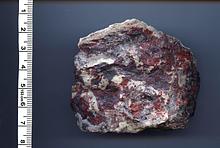
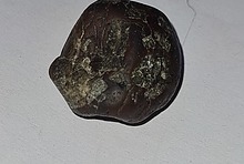
Now, having read these posts I have temporarily set aside the color correction problem and and wondering if much of my problem with focus and lack of depth of field may not be because of a mis-match between the camera and the scope, I am photographing rock chip samples where the chip size is on the order of .5 - 2mm and the features I am trying to illustrate are individual sand grains, grain/matrix boundaries etc. The grains are around 0.05mm - 0.5 mm across.
The attached photo is about the best I have done so far and I think it was more luck and than skill.
My camera/microscope set up is in an RV mobil lab setting less than 200 feet from drilling rig so vibrations were a significant problem. I reduced them some by setting the microscope on a 2 inch thick piece of foam.
Any thoughts or commenst will be very much appreciated

30th Oct 2012 16:30 UTCTony Peterson Expert
http://gemmacaelestis.ca/astro.html
but had never much thought about them for mineral microphotography. Now you've got me obsessing about the optical resolution of my macro lenses!
Which just goes to show again what a great resource MinDat is.....
Tony
30th Oct 2012 19:18 UTCEugene & Sharon Cisneros Expert
It is not only apparent that you are aware of Nyquist, but that you have optimized your astrophotography to its fullest. Your deep sky images are superb; nice work! And BTW, it’s not uncommon to find people doing both macro/microphotography and astrophotography. I have not yet applied myself to other than simple solar system astrophotography, but do visual observing from my observatory. And because of my engineering background, I fear that I spend far more time working on it than using it.
Anyway, I wouldn’t obsess over your objectives. They are what they are; ultimately limited by the immutable laws of optical physics and you can only aspire to squeezing out every bit of performance from them.
Cheers,
Gene
30th Oct 2012 21:00 UTCEugene & Sharon Cisneros Expert
I don’t believe that mismatch between your camera and microscope is a major problem. Your system is oversampled, for that microscope/camera, and is not gaining anything from having 10MP. The small pixel size means lower sensitivity, about ¼ that of a 3MP camera, and will necessarily result in longer exposure times. This may be part of your problem with vibrations. Even on a foam support, high frequency vibrations may be getting through. I notice on screen vibrations with my set up and it is well isolated by foam, etc.. My suggestion would be to increase illumination if possible, thereby causing the software to shorten the exposure time appropriately. This will help with vibrations. A 150W halogen fiber optic illuminator is a must for this.
As far as depth of field is concerned, it is the nature of the beast. Resolution and depth of field are mutually exclusive. If you want high resolution, then you must pay the piper by having less depth of field. There are ways around this (multi-focus technique), but it would not be conducive to getting images out in a timely manner.
I would also suggest updating the Toupview software to the latest version. It has a “One Touch” color balance feature that works very well and relieves one of the fiddling with the sliders.
Lastly, keep in mind that it is hard to compete with many of the photos presented on Mindat. The best of these are carefully set up "studio" shots, utilizing sophisticated techniques and equipment that do not lend themselves to field work. Practicing in a non-rushed environment, not in the field, may allow you to better develop your technique.
Gene
26th Jan 2013 01:35 UTCJonathan Zvonko Levinger Expert

26th Jan 2013 15:16 UTCDavid Von Bargen Manager
Direct link is now at
http://www.bigcatchusa.com/downloads/drivers-and-software/
29th Jan 2013 15:54 UTCJonathan Zvonko Levinger Expert
22nd Mar 2013 03:18 UTCJean-Michel
I tried to use the "Fusion" program coming in the CD ROM with the Amscope, it works but gives me a blurry result. So far, seems I didn't get mutch for my money. Some idea how make it work better ?
Thanks,
Jean-Michel Maes
Museo Entomologico de Leon
NICARAGUA
22nd Mar 2013 12:10 UTCOwen Lewis
You are experiencing difficulty with the depth-of-field limitation inherent in any optical system. Basically, this is the range of distances from the lens that can be imaged simultaneously in sharp focus by any given optical system. As a general rule, the higher the level of magnification of an optical system, the less the depth of field will be. Because of the way our brains work, we are able to overcome this limitation to a fair extent when viewing directly through a microscope (etc) but since a camera will capture only a static 2D view, the depth-of-field limitation is starkly reproduced in every camera image.
Thanks to fast PCs, digital cameras and inventive minds, it is now possible to remove the depth-of-field limitation from digital camera images. This is done by making not just one but many images, all of which have different and marginally overlapping camera focus settings. These multiple images are then combined into one single image with an apparent depth-of-field equal to the sum of the depths-of-field of all the different images recorded. This is done using an 'image-stacking' software program. Two good ones are Combine ZP (freeware) and Helicon Focus ( a commercial product).
Be warned that making the necessary set of images and combining them is time-consuming and laborious, However, if you have a camera the focussing of which can be remotely controlled from a computer, the Helicon Focus program becomes well worth the cost of buying it because of the time and work it will save you by making automatically a whole series of differently focussed images for you to give you a final product with the depth of field that you need.
22nd Mar 2013 16:08 UTCEugene & Sharon Cisneros Expert

Thanks for the clear explanation of multi-focus imaging. I find myself having to explain the basics of this technique over and over again to ad nauseam. To that end, I have tried to create a simplified text/graphical explanation that hopefully is easy to understand. Perhaps it can be improved on, but here is the first iteration. You can click on it for a larger version.
I would also like to mention that Zerene Stacker software is perhaps now the de-facto standard for stacking software. Zerene Stacker interfaces directly with the StackShot automated stage, so that the number of images and increment size are all seamlessly controlled from within the program. This greatly reduces the amount of effort and tedium involved with multi-focus imaging.
Cheers,
Gene
22nd Mar 2013 17:33 UTCOwen Lewis
As you say, the field is opening up. Not only are there cameras, the differential focussing of which can be software controlled by a suitable image stacker program (Helicon Focus) but there are also software controlled movable stages that are, perhaps, the best approach of all for those prepared to buy at the cost and complexity.
Here's a 'new kid on the block' you may not yet have seen. Scroll down for some nice pics.
http://www.tuplaneta.es/foros/viewtopic.php?t=17407
The products are so new that the company web-site is not yet up and running but the initial specs are impressive and the price interesting for those that are interested in the stepping stage approach to the problem. The stepping of the stage is in increments down to 1.6um!. Cost for stand, stage and robotics is > EUR 1,200 and another EUR 90.00 gets youi a software licence. I shall be waytching developments of this product line closely! :)-D
22nd Mar 2013 17:40 UTCEugene & Sharon Cisneros Expert
The “Fusion” program is actually a multi-focus processing program. To make use of it, you will have to take multiple images in accordance with the information provided in Owen’s and my previous post. However, my experience with that program has not been encouraging. I would suggest that you try the free CombineZ software.
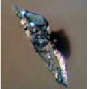
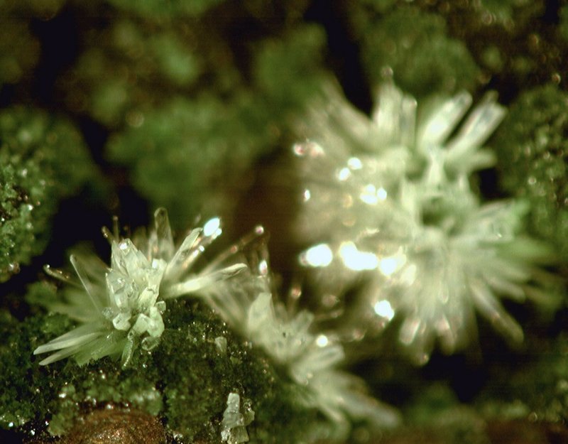
You didn’t mention which model of camera you have, but here are two examples taken with a 1.3MP version of the same camera that you have. The first is a single image that shows the depth of field problem. The second image is a composite of only six separate images that were carefully hand stepped with the microscope focus knob and processed with CombineZ. A better result could have resulted from a greater number of smaller increments, but for hand stepped it's not too bad.
Cheers,
Gene
Hemimorphite single image
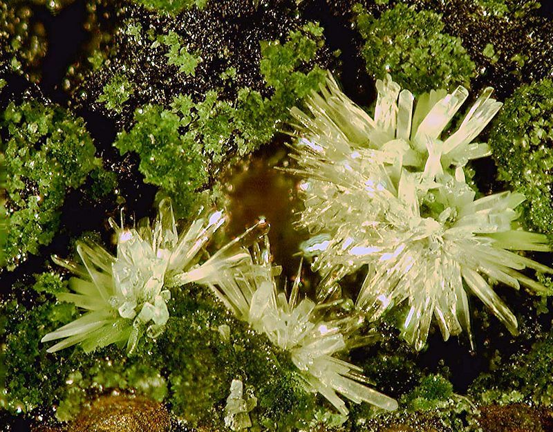
Hemimorphite stack of 6 images
22nd Mar 2013 21:13 UTCOwen Lewis
Worth looking at just for the slide show of micro specimens..... and I was wrong about the degree of control over the stepping. 1.6um is the standard offering. It seems that this can be further improved to 0.6um stepping, which should fully satisfy *any* maiden's prayer. Lovely shots of a Zeiss research grade 'scope intedgrated with this robotics rig.... all I need is to rob a bank...... . For those using Google as their web browser, turning on the auto-translate feature may help further.
22nd Mar 2013 23:24 UTCField Yu
http://www.touptek.com/download/
May be this can fix your problem.
Also their FAQ is great
Field
14th Oct 2013 17:10 UTCFernandez Oscar
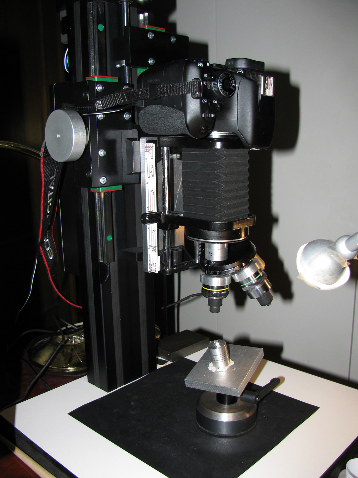
I have participated in the design of MacroRail, not just a simple product or an focus rail, it is a complete solution with professional quality. The MacroRail no less than weighs 12 Kgs.
The standard model Works with 1.6 microns (mechanical and engine use). If we use electronical micro stepping features we can work to 0.1 microns.
Works very well with head of trinocular microscope (until 30 kgr) or directly with camera, bellows, etc..
We evolution the product and the software to Improve more functionality. Now we working in Macro3D solution (Macrophtography + 3D/360 º).
Not is a cheap solution but if you want quality you have to pay. Many times we spend much more on the camera or on any lens or another accessories.
Regards, Oscar.
11th Nov 2013 14:34 UTCOwen Lewis
I was looking at the vertical Macrorail again this morning with a view to a possible purchase. However, I think I see a problem. My trinocular microscope head is of the common design that has a push/pull rod that rotates a prism, deflecting the light train from the right eyepiece port to the camera port. The knob for this extends out fron the pod shell and requires about 20mm clearance between the Macrorail vertical support and the cover of the pod. The photo at shows only a binocular(!) port pod fitted and no clearance at all for knob on the push rod for the trinocular port. The photo presently on the Macrorail site shows only a sideways displaced camera mounting and port (as used exclusively by Zeiss on selected models of microscope and by Wild (now owned by Zeiss?).
Do you have any comment on this issue that would seem to make Macrorail as presently configured only suitable for use with either a port that has no manually operated arrangement for moving a prism from one alignment to another or else is a binocular (not trinocular) pod with a camera fitted via an eyepiece adapter into one of the eyepiece tubes.
Any comment? Do Macrorail offer a 76mm ring supporting arm that will give the necessary clearance to use a trinocular ported microscope pod of the common design?
11th Nov 2013 15:48 UTCFernandez Oscar
You can see one Trinocular MacroRail Setup. It's not the more recently version but you can see. We replace the micrometers with aluminium pieces like my current setup:
http://MacroRail.com/imagenes/IMG_4152.JPG
I use directly the camera with bellow and microscope objectives (Nikon BD 5x, 10x & 20x) and photo enlarger objective (componon-s).
You can see in the picture test take photo to one diamond for gemologists.
You can see the accessory piece in the first & third picture of trinocular setup. This piece is build specific of your setup/needs.
Send me a picture of you current trinocular and the make and model to oscar (@) macrorail.com and we study the accessory that you need.
We have manufactured many accessories for various makes and models of loupes trinocular.
Regards, Oscar.
11th Nov 2013 18:13 UTCFernandez Oscar
Not is a problem, we can desing the adapter for you trinocular with more distance between the MacroRail and your trinocular. See the next image:
http://www.gem-sphalerite.com/external/forum_go/macrorail/macrorail-1.JPG
You see a distance about 20 milimeter but we can build with 50mm or more.
The MacroRail is very robust and not present problems.
The accessory cost 65€ for all designs.
Regards, Oscar.

11th Nov 2013 20:39 UTCJolyon Ralph Founder
Thank you.


Mindat.org is an outreach project of the Hudson Institute of Mineralogy, a 501(c)(3) not-for-profit organization.
Copyright © mindat.org and the Hudson Institute of Mineralogy 1993-2024, except where stated. Most political location boundaries are © OpenStreetMap contributors. Mindat.org relies on the contributions of thousands of members and supporters. Founded in 2000 by Jolyon Ralph.
Privacy Policy - Terms & Conditions - Contact Us / DMCA issues - Report a bug/vulnerability Current server date and time: April 18, 2024 14:02:10
New Idria Mining District, San Benito County, California, USA