Home PageAbout MindatThe Mindat ManualHistory of MindatCopyright StatusWho We AreContact UsAdvertise on Mindat
Donate to MindatCorporate SponsorshipSponsor a PageSponsored PagesMindat AdvertisersAdvertise on Mindat
Learning CenterWhat is a mineral?The most common minerals on earthInformation for EducatorsMindat ArticlesThe ElementsThe Rock H. Currier Digital LibraryGeologic Time
Minerals by PropertiesMinerals by ChemistryAdvanced Locality SearchRandom MineralRandom LocalitySearch by minIDLocalities Near MeSearch ArticlesSearch GlossaryMore Search Options
The Mindat ManualAdd a New PhotoRate PhotosLocality Edit ReportCoordinate Completion ReportAdd Glossary Item
Mining CompaniesStatisticsUsersMineral MuseumsClubs & OrganizationsMineral Shows & EventsThe Mindat DirectoryDevice SettingsThe Mineral Quiz
Photo SearchPhoto GalleriesSearch by ColorNew Photos TodayNew Photos YesterdayMembers' Photo GalleriesPast Photo of the Day GalleryPhotography
╳Discussions
💬 Home🔎 Search📅 LatestGroups
EducationOpen discussion area.Fakes & FraudsOpen discussion area.Field CollectingOpen discussion area.FossilsOpen discussion area.Gems and GemologyOpen discussion area.GeneralOpen discussion area.How to ContributeOpen discussion area.Identity HelpOpen discussion area.Improving Mindat.orgOpen discussion area.LocalitiesOpen discussion area.Lost and Stolen SpecimensOpen discussion area.MarketplaceOpen discussion area.MeteoritesOpen discussion area.Mindat ProductsOpen discussion area.Mineral ExchangesOpen discussion area.Mineral PhotographyOpen discussion area.Mineral ShowsOpen discussion area.Mineralogical ClassificationOpen discussion area.Mineralogy CourseOpen discussion area.MineralsOpen discussion area.Minerals and MuseumsOpen discussion area.PhotosOpen discussion area.Techniques for CollectorsOpen discussion area.The Rock H. Currier Digital LibraryOpen discussion area.UV MineralsOpen discussion area.Recent Images in Discussions


Mineral PhotographyGizmo for stacking - new scope

7th Nov 2009 16:59 UTCRon Gibbs
I purchased Helicon Focus for increasing depth of field a few of months ago and wanted to use it with the new system. I shot several images but was not happy with the test results. I decide the problem was controlling the overlap factor between images. For those who don't know about Helicon Focus it works by taking a series of images each with a slightly different focus point on the sample. The software then picks the sharp part of each photo and applies them to a single image. The result is vastly increased depth of field.
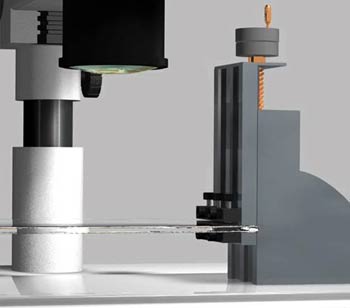
I needed to control the positioning of the sample at even increments with good control down to small fractions of an inch. I decided to built a gadget to accomplish this. I got a milling attachment from Taig Tools. It is a micro adjuster connected to a small vise mechanism. Taig Tools
I attached the base of the unit to a piece of flat polycarbonate and made a small polycarbonate shelf for the vise to hold. When the knob is rotated the shelf can be moved in a controlled fashion. The adjustment control is calibrated in thousandths of an inch. A photograph of the gadget is shown below with a small mineral sample of vanadinite. Photo below ...
Device
The gadget is placed under the lens of the microscope and focus is first achieved at the highest point on the sample using the focus knob on the scope. A photograph is taken, the knob on the gadget is then adjusted to raise the sample a fixed amount. In the example below I used 5/1000 of inch for each increment. I ended up shooting about 50 images as the sample moved through all of the focus planes. Here is the unit positioned under the scope.
Device in place
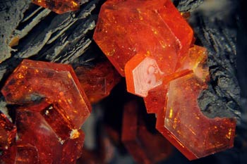
This first image shows the first photograph recorded before the set of images were enhanced with Helicon Focus. Notice the top edge of one crystal is in focus the remainder of the image is well out of focus. The width of the entire image is 10 mm.
First image in stack
The next image was created using the stack of photos in Helicon Focus. It is very apparent that the image now shows good focus throughout the range. The gadget works well in controlling the sample's rise through the various focal planes.
Stack Results
As for my set up I have a Macintosh so there are limited software programs to do the stacking. I have no clear favorite between the two packages with the best interface (in my opinion), I simply purchased Helicon before I ever found Zerene. I can't afford to by them all!
Here is a short animated movie I made with Cinema4D showing the device in use. It's not 100% complete but close enough for now. I will use it in some training slides next year. It giveS a reasonable depiction of the new scope set up.
Short Movie
(You will need Quicktime to run it)
7th Nov 2009 23:56 UTCHoward Messing
8th Nov 2009 02:08 UTCRon Gibbs

8th Nov 2009 14:53 UTCDominik Schläfli Expert

8th Nov 2009 15:09 UTCJames Christopher
9th Nov 2009 04:38 UTCRon Gibbs
As far as moving verses stationary light ... You got me ... sort of.
I have proved to myself it doesn't matter.
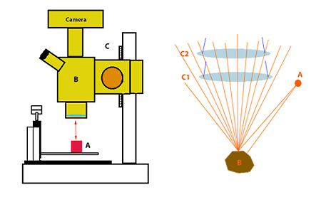
Lets look at the fist diagram below and not be concerned for a minute about the position of the lights. We first need to agree that moving the object on the platform up toward the main objective lens is no different than moving the microscope(B> down toward the object(A). When we use the large or fine focus knob we are actually moving the entire scope body(B> up or down the base-connecting pole. We are adjusting a worm gear(C) that makes the actual travel happen. Hence only an observer looking from the outside would know if the sample got moved or the scope got moved.
Diagram 1
The only change in the system in the distance between the main capture ocular in the bottom of the scope and the subject matter (object A).
Now lets consider three different lighting scenarios:
Case 1.) light coming straight down from the axis of the viewing lens. (Some scopes actually offer an attachment that provide light through the viewing lens system.) Mine does not have this feature, but if the demo scope in the diagram did, then the lighting would not change whether the scope or the sample moved. The light being connected to the viewing axis and the direction of motion only provides a mechanism for the intensity of the reflection to change. Light falls off by 1/R2 (R squared).
Now this is true for any position of the lights you choose. Even if we keep the distance between the original light and the sample(A) fixed, the other distance (the reflected light) changes by the 1/R2 rule as that distance will change regardless of which moved.
As far as moving the light source with the sample, I did do this initially, not so much to control the various light angles, but because I wanted to use a ring light on the scope and it would typically sit around the main objective housing. So if any of you are currently using this set up then moving then focusing the microscope for multiple image taking will have the same "changing the light" effect as moving the sample.
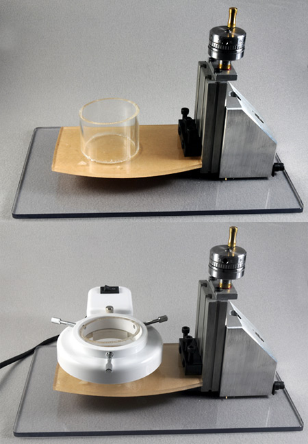
The idea of using a ring light is to provide even 360 degree illumination and negate this effect. The light is also located as near to the center of focus as possible like the interior lens-light described above, again mitigating the effect. The little gadget I first made is pictured below. I wanted to keep the light as close to the object (sample) as possible to get maximum illumination. I used a plastic cylinder on the moving base and put the sample into the center of it The light was clamped on the outside of the cylinder and the whole unit moved up and down with the slide. Thus the lighting was effectively constant without regard to position. See next photos ...
Moving Light
I discovered that this introduced a new problem which is related to the lighting set-up I will describe below. The light being located near the sample top or an equatorial position on "some" samples produced internal shadow or (more accurately) added diffusion in the sample and provided poor viewing. This was the case in some gemstones where the internal flaw (item of interest) was surrounded by a veil or tiny bubbles.
Case 2.) Assume the light is at nearly a right angle to the object being photographed. If there is only one light source from one side or the other, then a strong shadow is produced on the opposite side. Think of this as the "sun-rise" or "sun-set" scenario. A small change in position of the object, will cast a much wider or shallower shadow with relatively little movement up or down. Thus during morning or night, in the "big" real world shadows are elongated to a high degree and seem to grow or shrink rapidly as the sun sets or rises. I submit in most microscopy photographs we try NOT to use this set up. We supply multiple light sources to open shadow areas. The only time the effect might be warranted is if we need to accentuate a very fine pattern in a sample. For example really fine etch lines is a crystal surface.
If you are trying to light a more or less clear gemstone to highlight an internal feature this lighting can backfire if the feature is within a cloud of other features. If the other features are solid, then they cast little shadows on the object of interest, or if they are translucent they will scatter the light making focus very poor.
Case 3.) light from above but not concentric with the focal axis. In most of my work I use multiple light sources to surround the object being photographed. This is done not just to reduce shadows but also to get sufficient light on the image for reasonable photography. Microscopes "eat light" in their precision and fine optics. Just like the low depth of field problem in a scope, the light passing through multiple layers of even "fine optics" continues to diffuse and remove light.
One thing which helps remove shadows and limit specular highlights is to use diffuse light. This works against the "intensity/strengthening" effect of light, but diffuse light really helps eliminate strong specular reflections where all information is lost. If you look at the second part of the first diagram there is a poor but roughly accurate light path map for a light being reflected from a crystal located below. (Yes it's an over simplified image, there are actually an infinite number of cones rising up from all positions in the sample ... that's just too hard to draw!)
Reflect light never comes from a true point source, and unless the reflected surface is nearly a perfect mirror, it diffuses the reflection itself. The reflected light from a typical light source (even a halogen fiber optic) produces cones of reflection and they spread-out as they travel away from the object. Only those outer most parts of each cone that actually strike the object lens (C1 and C2 in diagram) can be bent back and used to construct the image. Any falling outside the objective lens continue passing on to oblivion as far as the image is concerned. When we change the distance between the objective and the object being photographed we change the "field of view" of the final image. Hence some cones exit in the lower C1 position that will miss entirely in the higher C2 position.
SImple test, put a mm scale under the scope in place of the sample. Set the focus on the scope then adjust the magnification so that the outside edges to two mm markers just appear touching the edge of the field of view. Now move the fine focus knob two full revolutions in either direction. The two markers that were on the edge of the field of view will now be inside or outside the field. This means that items in the original field have either grown or shrunk slightly. Hence light angles hitting portions of them have change in the image.
Or ... look at the first and last photo in a deep stack of images, the outside edge cannot line up as the one taken from one end of focus are not present in the other. The good news for most of us is that much of the software we use will reposition the images in the stack or provide a means for us to do it.
From my (and I admit) limited experience thus far in stacking, if the lighting for the microscope is diffuse and relatively even, this will easily negate the changes in direction from stationary light source and the moving sample. (Basically one of the prime ideas in using a ring light.) Hence after doing about a couple dozen sets of images I have mostly stopped using the moving ring light, I see no major advantage. The only problem I do see is that when I poorly light a subject the specular reflections tend to be slightly larger than they should be. They appear to migrate slightly and broaden.
I personally believe we often spend a way too much time worrying about the "perfect system", there is no such thing. Everything we do to enhance one thing will always negatively effect another. Physics provides us with the saying ... there is no free lunch! Find a system that works for you and turn out results. I think it great to read about what others are doing as it aids us in our own learning and helps us see things in a different way. I enjoy seeing the gadgets and gizmos other use to solve problems.
12th Nov 2009 14:52 UTCRoberto Bracco
I agree that diffuse light is mandatory in most cases - unless you have a really dull subject - and solves a lot of problems, especially ghost off-focus lights coming out from everywhere.
I only think 5/1000", i.e. 0.127mm, steps for a 10mm field are a little overkill - in my saw-and-hammer experience such a fine step works well for 3-4 mm fields (my micrometer screw is a heavier, much less "clean", version of your setup, and moves by 0.01mm steps).
12th Nov 2009 19:08 UTCRon Gibbs
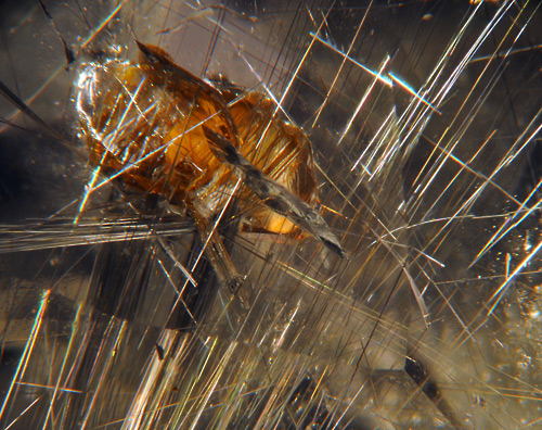
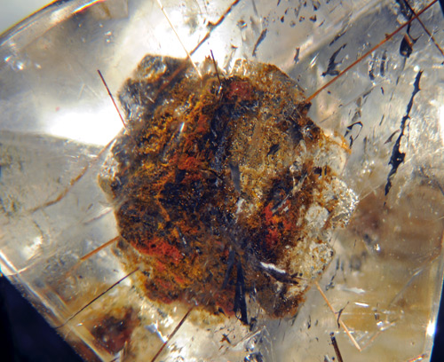
The first stone is a cut (faceted) piece of quartz with imbedded anatase and rutile crystals. The second two were puchased as ankangite in quartz and the smaller of the two actually is. The larger (center stone) may have ankangite in it, but the more interesting inclusion is a silver colored metallic looking crystal.
The anatase, rutile, and what appears to be the remainder of a licorice twist
Anatase (~3mm) & Rutile
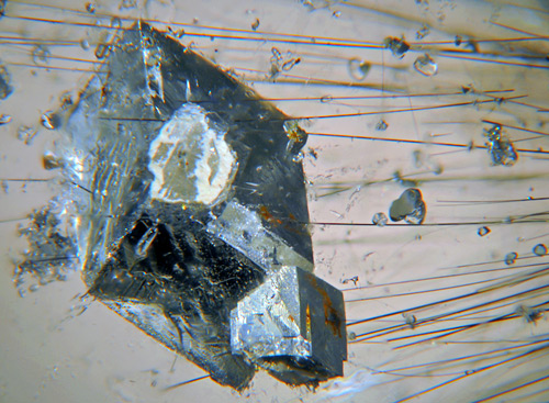
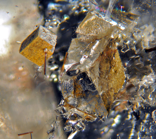
This is the interesting inclusion in the second stone. These stones supposedly had a mix of ankangite and celsian, but neither mineral should look like this crystal. The thin crystals at the edges may well be ankangite. (Update - the metallic looking inclusion is celsian with an air gap around it making it look like a mirror/metallic surface. - direct from a e-mail form the seller!)
Ankangite & Celsean (~3mm)
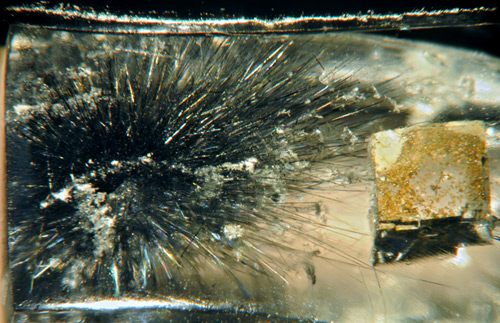
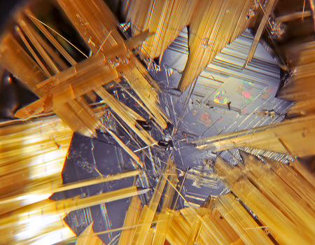
This is from the smallest cut stone, and it appears to be a cluster of ankangite needles with another pseudo metallic cubic material to the right. Another interesting unknown in the mix.
Ankangite & ? (~1mm)
When you finally get around to the stuff you bought nearly a year ago, you actually find some very interesting things. Glad I got to do most of them done before I took off to Tucson again this year. I guess you should really take the time to examine what you have already purchased!
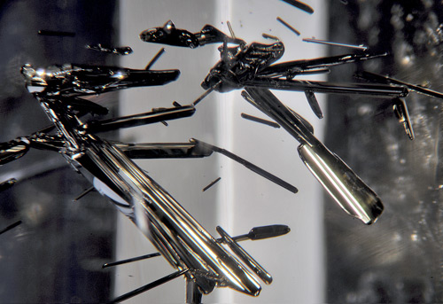
Purchased as stibnite clusters in a quartz gem. The larger cluster is about 3 mm in length. (Update from e-mail from sample provider - it was sold as stibnite, but has since been analyzed as Jamesonite, perhaps after stibnite.)
Jamesonite (Stibnite?)
Two different samples of dolomite in quartz. The first is a real "bolder", it's about 4mm in size by itself. The second pair is a good deal smaller, the little one impaled by the rutile crystal is just under 1mm.
Dolomite
Dolomite
Finally a hematite with rutile in quartz cabochon.
Hematite (~3mm)/rutile
Most of these samples were purchased from Marco Campos Venuti, he had a room in the Pueblo Inn (now RappaRiver Show) and had more samples of included stones than I saw anywhere else by a wide margin.
I agree the step size is finer than needed but it is the large notch on the micrometer and easy to see and quick to position on without additional lighting and higher power glasses on me!. I am still not totally happy with the results or the set up, but it's new to me and I will fine tune it as I move ahead. Still lots of room for improvement.
_________________
18th May 2010 03:59 UTCEugene Cisneros
I just happened upon this thread and your comment regarding automatic stacking. You may find my article entitled "Automated Multi-focus Imaging", in the Mineralogical Record's online journal, to be interesting.
http://mineralogicalrecord.com/journal.asp
Regards,
Gene


Mindat.org is an outreach project of the Hudson Institute of Mineralogy, a 501(c)(3) not-for-profit organization.
Copyright © mindat.org and the Hudson Institute of Mineralogy 1993-2024, except where stated. Most political location boundaries are © OpenStreetMap contributors. Mindat.org relies on the contributions of thousands of members and supporters. Founded in 2000 by Jolyon Ralph.
Privacy Policy - Terms & Conditions - Contact Us / DMCA issues - Report a bug/vulnerability Current server date and time: May 8, 2024 18:57:54